


| Main | |
| Product Series | UEC1 |
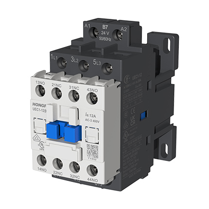
| Product or Component Type | Contactor |
| Device Short Name | UEC1-12D |
| Contactor Application | Motor control Resistive load |
| Utilisation Category | AC-3 AC-4 AC-1 |
| Poles Description | 3P |
| Rated Operational Voltage [Ue] | Power circuit: ≤ 690 V AC 50/60Hz |
| Rated Operational Current [Ie] | 12 A (at ≤60 °C) at ≤ 400 V AC AC-3 for power circuit 25 A (at ≤60 °C) at ≤ 690 V AC AC-1 for power circuit |
[Us] Control Circuit Voltage (AC 50/60Hz) | Voltage (V): 24 36 42 48 110 115 127 220 230 240 380 400 415 |
| Code: B7 CC7 D7 E7 F7 FE7 FC7 M7 P7 U7 Q7 V7 N7 | |
| Complementary | |
| Motor Power kW | 3 kW at 220/230 V AC 50/60 Hz (AC-3) 5.5 kW at 380/400 V AC 50/60 Hz (AC-3) 7.5 kW at 660/690 V AC 50/60 Hz (AC-3) |
| Motor Power hp | 1 hp at 110…120 V AC 50/60 Hz for 1 phase motors 2 hp at 200…208 V AC 50/60 Hz for 1 phase motors 2 hp at 220…240 V AC 50/60 Hz for 1 phase motors 3 hp at 200…208 V AC 50/60 Hz for 3 phases motors 3 hp at 220…240 V AC 50/60 Hz for 3 phases motors 7.5 hp at 440…480 V AC 50/60 Hz for 3 phases motors 10 hp at 550…600 V AC 50/60 Hz for 3 phases motors |
| Pole Contact Composition | 3 NO |
| Conventional Free Air Thermal Current [Ith] | 25 A (at ≤60 °C) for power circuit 10 A (at ≤60 °C) for signalling circuit |
| Rated Short-Time Withstand Current [Icw] | 105 A ≤40 °C - 10 s for power circuit 210 A ≤40 °C - 1 s for power circuit 30 A ≤40 °C - 10 min for power circuit 61 A ≤40 °C - 1 min for power circuit |
| Associated Fuse Rating | 10 A gG for signalling circuit conforming to IEC 60947-5-1 25 A gG at ≤ 690 V coordination type 2 for power circuit |
| Average Impedance | 2.7 mΩ - Ith 50 Hz for power circuit |
| [Ui] Rated Insulation Voltage | Power circuit: 690 V conforming to IEC 60947-4-1 Power circuit: 600 V UL Certified Signalling circuit: 690 V conforming to IEC 60947-5-1 Signalling circuit: 600 V UL Certified |
| Overvoltage Category | III |
| Pollution Degree | 3 |
| [Uimp] Rated Impulse Withstand Voltage | 6 kV conforming to IEC 60947 |
| Mechanical Durability | 10 M cycles |
| Electrical Durability | 1.5 M cycles 12 A AC-3 at Ue ≤ 400 V |
| Control Dircuit Type | AC at 50/60 Hz standard |
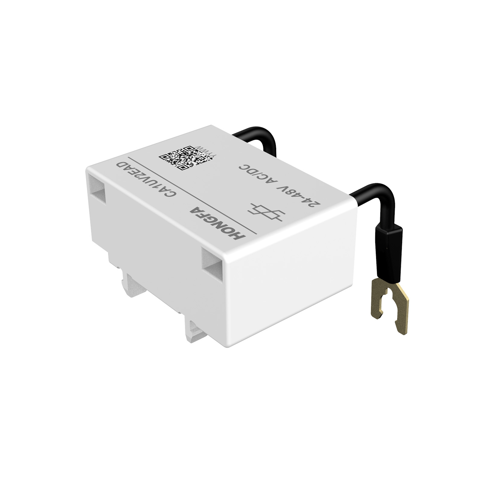
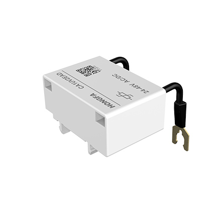
| Coil Technology | Without built-in suppressor module |
| Control Circuit Voltage Limits | 0.8...1.1 Us (-40…60 °C): operational AC 50 Hz 0.85...1.1 Us (-40…60 °C): operational AC 60 Hz 1...1.1 Us (60…70 °C): operational AC 50/60 Hz 0.2...0.75 Us (-40…70 °C): drop-out AC 50/60 Hz |
| Inrush Power in VA | 75 VA 50/60 Hz (at 25 °C) |
| Hold-in Power Consumption in VA | 9.5 VA 50/60 Hz (at 25 °C) |
| Operating Time | Power circuit: 12...22 ms closing, 4...19 ms opening Signalling circuit (NO): 15...26 ms closing, 4...19 ms opening Signalling circuit (NC): 4...19 ms opening, 12...32 ms closing |
| Maximum Operating Rate | Electrical: 1000 cycs/h Mechanical: 3600 cycs/h |
| Connections - Terminals | Power circuit: screw clamp terminals 1 1…6 mm² (AWG 18…10)- cable stiffness: flexible without cable end Power circuit: screw clamp terminals 2 1…6 mm² (AWG 18…10)- cable stiffness: flexible without cable end Power circuit: screw clamp terminals 1 1…6 mm² (AWG 18…10)- cable stiffness: flexible with cable end Power circuit: screw clamp terminals 2 1…4 mm² (AWG 18…12)- cable stiffness: flexible with cable end Power circuit: screw clamp terminals 1 1…6 mm² (AWG 18…10)- cable stiffness: solid without cable end Power circuit: screw clamp terminals 2 1…6 mm² (AWG 18…10)- cable stiffness: solid without cable end Control circuit: screw clamp terminals 1 1…4 mm² (AWG 18…12)- cable stiffness: flexible without cable end Control circuit: screw clamp terminals 2 1…4 mm² (AWG 18…12)- cable stiffness: flexible without cable end Control circuit: screw clamp terminals 1 1…4 mm² (AWG 18…12)- cable stiffness: flexible with cable end Control circuit: screw clamp terminals 2 1…2.5 mm² (AWG 18…14)- cable stiffness: flexible with cable end Control circuit: screw clamp terminals 1 1…4 mm² (AWG 18…12)- cable stiffness: solid without cable end Control circuit: screw clamp terminals 2 1…4 mm² (AWG 18…12)- cable stiffness: solid without cable end |
| Tightening Torque | Power circuit: 13 lb.in(1.5 N·m)- on screw clamp terminals - with screwdriver flat Ø 6 mm Power circuit: 13 lb.in(1.5 N·m)- on screw clamp terminals - with screwdriver Philips No 2 Control circuit: 11 lb.in (1.2 N·m)- on screw clamp terminals - with screwdriver flat Ø 6 mm Control circuit: 11 lb.in (1.2 N·m)- on screw clamp terminals - with screwdriver Philips No 2 |
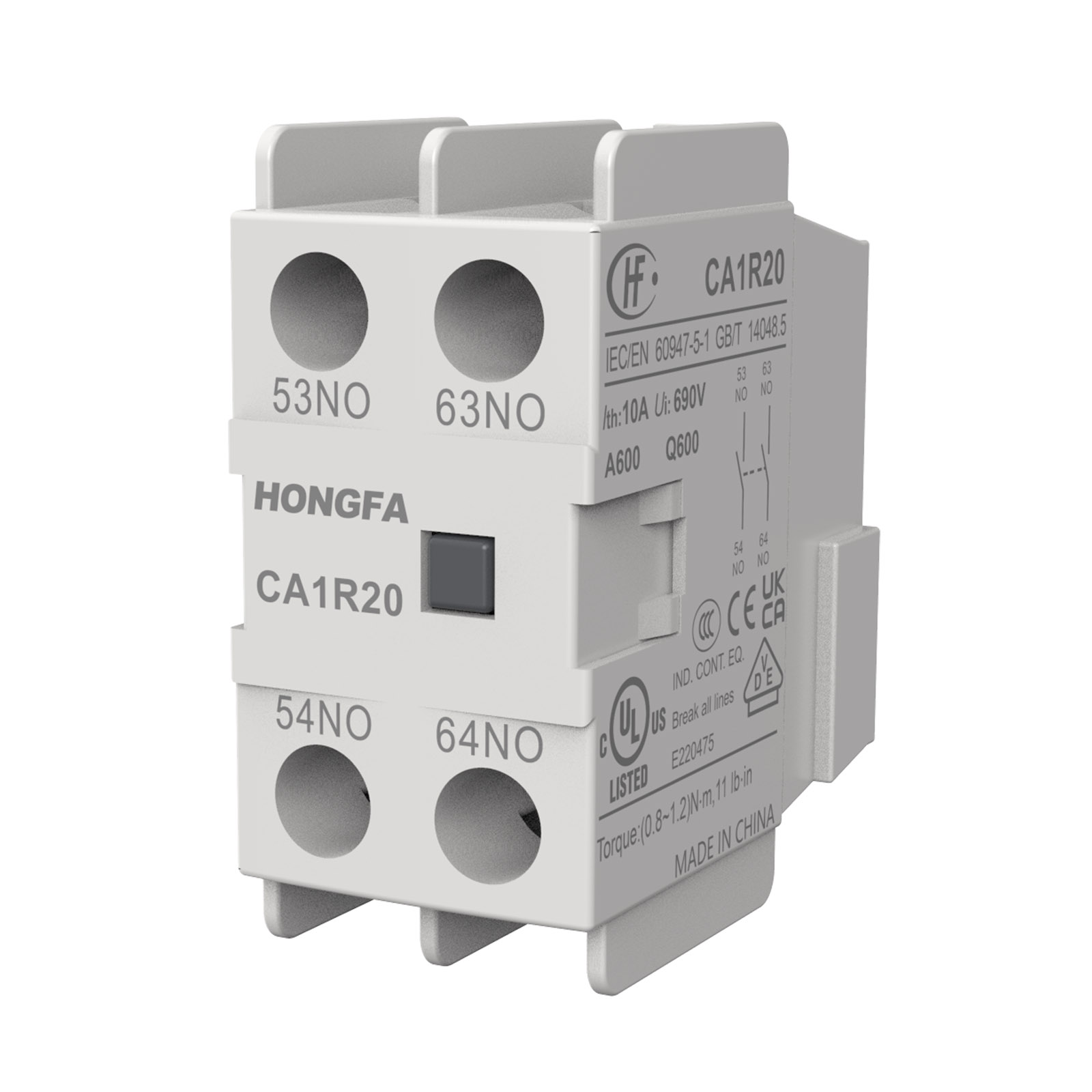
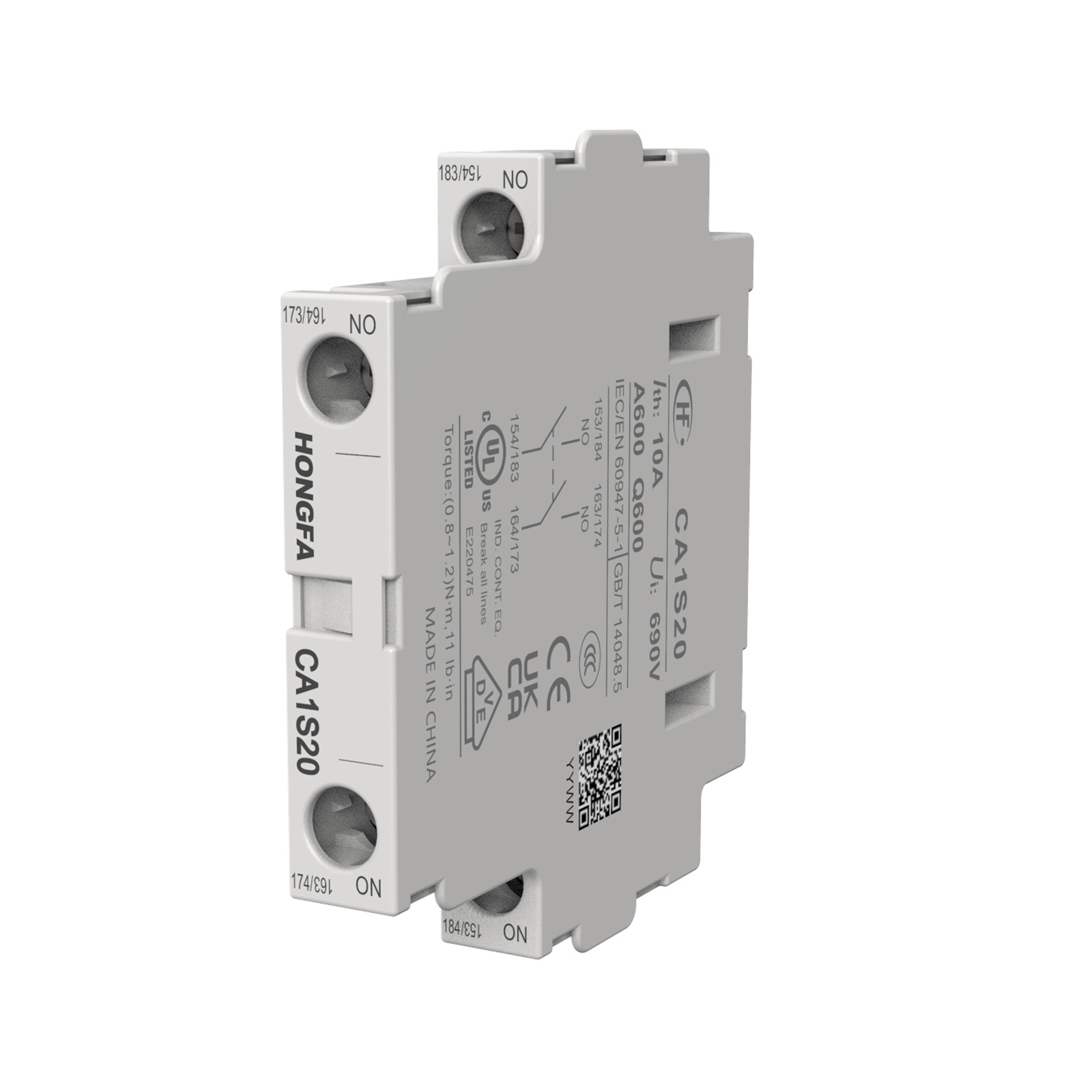
| Auxiliary Contact Composition | 1NO1NC,2NO2NC,other combinations can be customized |
| Minimum Switching Voltage | 24 V for signalling circuit |
| Minimum Switching Current | 0.1A for signalling circuit |
| Insulation Resistance | > 10 MΩ for signalling circuit |
| Mounting Support | Screw 35mm DIN Rail |
| Environment | |
| Standards | GB/T 14048.4,GB/T 14048.5, IEC/EN 60947-4-1,IEC/EN 60947-5-1, BS EN 60947-4-1,BS EN 60947-5-1,UL 60947-4-1,UL 60947-5-1 |
| Product Certifications | CCC,CE,UKCA,VDE, UL (cULus LISTED) |
| IP Degree of Protection | IP20 front face conforming to IEC 60529 |
Permissible Ambient Air Temperature Around the Device | -40…60 °C for normal operating 60…70 °C with derating (for operation in the range of Us...1.1Us) Storage: -60…80 °C |
| Operating Altitude | 0...3000 m without derating |
| Fire Resistance | Current-carrying parts:850 °C conforming to IEC 60695-2-11 |
| Height | 90 mm |
| Width | 45 mm |
| Depth | 96 mm |
| Net Weight | 0.42 kg |
| Packing Units | |
| Unit Type of Package 1 | 1 box |
| Number of Units in Package 1 | 1 pcs |
| Package 1 Height | 10.4 cm |
| Package 1 Width | 5.0 cm |
| Package 1 Length | 9.5 cm |
| Package 1 Weight | 0.48 kg |
| Unit Type of Package 2 | 1 carton |
| Number of Units in Package 2 | 30 pcs |
| Package 2 Height | 25.0 cm |
| Package 2 Width | 29.0 cm |
| Package 2 Length | 32.5 cm |
| Package 2 Weight | 14.40 kg |
| Offer Sustainability | |
| REACH Regulation | Conforming |
| EU RoHS Directive | Conforming |
| Mercury Free | Yes |
| China RoHS Regulation | Conforming |
| RoHS Exemption Information | Yes |
| Contractual Warranty | |
| Warranty | 18 months |
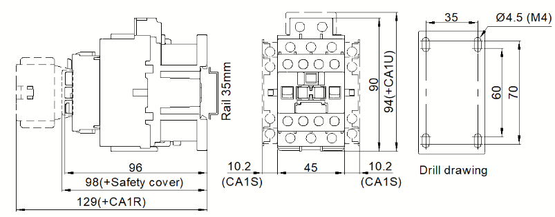
Dimension
UEC1-09…18(3 poles) UEC1-09…18(3-Pole)
Control Circuit: AC
AC Contactor:
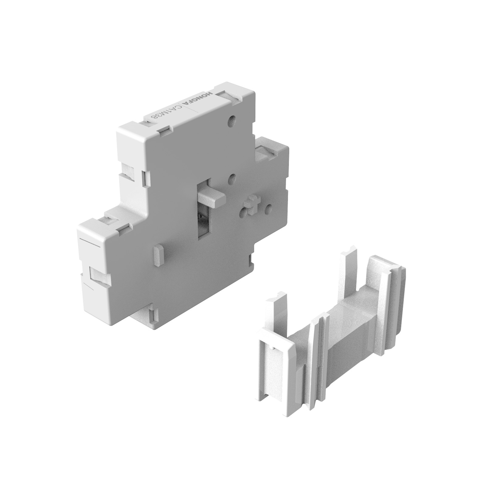
Mechanical Interlocking Contactor:
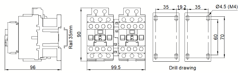
Note: unit mm. The unannotated tolerance of the mounting hole size is +/-0.5, and the unannotated tolerance of the rest of the product's external dimensions is +/-1.5 unless otherwise specified.